Passive Low Pass Filter (RC & RL) — Cutoff Frequency, Formulas, and Complete Guide
A passive low pass filter is one of the simplest and most important circuits in analog electronics. It allows low-frequency signals to pass while attenuating higher frequencies, making it essential for audio processing, signal conditioning, noise filtering, sensors, and smooth DC outputs. In this guide, you’ll learn exactly how RC and RL low pass filters work, how to calculate the cutoff frequency, their frequency response, phase shift, and how to design them correctly for electronics projects.
What you'll learn
1. What is a Passive Low Pass Filter?
A passive low pass filter is built only with passive components (resistor, capacitor, or inductor). Its role is to reduce the amplitude of frequencies above a specific threshold known as the cutoff frequency. These filters exist in two common forms:
RC Low Pass Filter (Resistor–Capacitor)
RL Low Pass Filter (Resistor–Inductor)
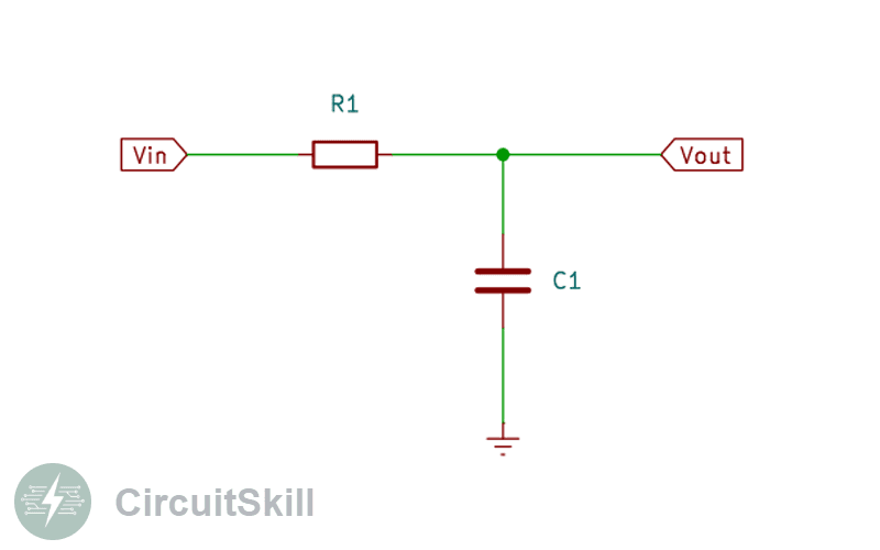
2. RC Low Pass Filter
This is the most common type. The input signal passes through a resistor, and a capacitor is connected to ground. At low frequencies, the capacitor behaves like an open circuit, allowing the signal to pass. At high frequencies, it becomes a short circuit, diverting the signal to ground and attenuating it.
Cutoff Frequency Formula (RC):
The cutoff frequency is where the output drops to 70.7% of the input (–3 dB point).
Fc = 1 / (2πRC)
Voltage Gain Formula (RC):
|H(f)| = 1 / √(1 + (2πfRC)²)
Phase Shift Formula (RC):
φ(f) = -arctan(2πfRC)
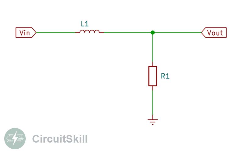
3. RL Low Pass Filter
In an RL low pass filter, the input passes through an inductor, and the resistor is connected to ground. Inductors resist high-frequency changes, which naturally produces attenuation at higher frequencies.
Cutoff Frequency Formula (RL):
Fc = R / (2πL)
Voltage Gain Formula (RL):
|H(f)| = R / √(R² + (2πfL)²)
Phase Shift Formula (RL):
φ(f) = -arctan(2πfL / R)
4. Frequency Response & Bode Plot
Both RC and RL low pass filters share the same behavior:
- 0 dB gain in the passband (low frequencies)
- –20 dB/decade attenuation after the cutoff frequency
- Phase shifts from 0° to –90° depending on frequency
5. Applications of Low Pass Filters
- Audio smoothing and tone control
- Noise reduction in sensor signals
- Anti-aliasing filters for ADCs
- Power supply ripple reduction
- Signal conditioning in embedded systems
6. How to Design a Low Pass Filter
The key is choosing the right cutoff frequency for your application.
Step-by-step design:
- Choose your desired cutoff frequency (f_c).
- Select two component values that satisfy the formula.
- Verify the output amplitude at your operating frequencies.
- Simulate or test the circuit with a function generator.
Example for RC Filter:
If you want fc = 1 kHz and choose R = 1 kΩ:
C = 1 / (2π × 1,000 × 1,000) ≈ 159 nF
7. Advantages of Passive Low Pass Filters
- Simple and low cost
- No power supply required
- Reliable and easy to build
8. Limitations
- Cannot provide gain
- Sensitive to load impedance
- Limited performance at very low or very high frequencies
Understanding low pass filters is fundamental to electronics design. Whether you're smoothing signals, cleaning noise, or preparing signals for conversion, mastering RC and RL low pass filters gives you essential control over frequency behavior in your circuits.
Need Clarification?(-10/req)
AIcredits:0